Automobiles Forum banner
1 - 20 of 21 Posts

JimK

· Registered
Joined
·
10 Posts
Discussion starter · #1 ·
Have an opportunity on an upgrad to a IC but before sinking money into the upgrade, I need to know if the Ic will drive a 4 wire GM IAC. The wiring connection diagrams (pinouts) do not show the 4 wires needed for a IAC. I use a 4 wire IAC now and know how to set one up and wouldn't run without it. Can the capability of the IC handle it and where can I find firm information on this?
 
JimK.

The 1C didnt have enough pins available on the single connector to allow us to provide it, so the 1C does not have 4 wire IAC capability.

The 2C does though.

1C idle control is limited to a 2 wire PWM valve, or an external temp based air bleed.
 
Discussion starter · #3 ·
Jim, I apologize, that reply is not correct, I have spoken to Dan about it and he knows that but apparently was not thining straight when he fired off that email to you.

As Jarrid has stated, the Ic does not include any built in idle control hardware as the Stage II ECU's do.

Thank you,
 
Where can I find the Pin ID's and wiring diagram for the GM IAC to a 11c 034 ECU?

I bought a new flying lead harness and can't seem to find clear directions on how to wire it, or my AAN TPS connector to the new harness.

THX
 
I have that.. I need to ID the pins on the TPS end of the harness... is there a diagram or are there any markings I can follow @ TPS and IAC Motor connectors?

The harness I have seems to have 2 twisted/shielded cables, one for VR Sensor/Reluctor has 2+shield, one for TPS has only 3wires + shield, not 4 white/____ as described by the pinout diagram.
 
I think there is some mass confusion goin on here. None of the TPS wires are shielded, the only shielded wires in the harness are crank and cam position. As described in the pinout the TPS sensor only has 3 wires, purple, yellow/red, and black.

The IAC has 4 white/___ wires, is that what you are referring to? The IAC and it's connector has pins labelled a,b,c,d which are referenced in that pinout I linked.
 
Yes sorry I am asking about both the IAC Stepper motor AND the TPS...

3 of the 4 white/____ wires were found in a twisted/shielded (white wrapper) cable into the harness... there is another Twisted/Shielded wire on the flying lead harness I got with one wire + shield that I assumed is the VR cable...

We stripped it way back and found only 3 wires inside????

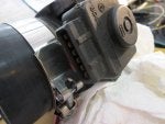
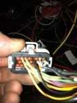
Here is the TPS I have, pretty sure it's from AAN. Pinout does not refer clearly to which of these marked 1-2-3-4-5-6 on my TPS pictured, or the connector I got, which fits and has the same 1-2-3-4-5-6 markings... which should I connect to??? I assume from the "034 Connector B" pinout that I will use 3 of them and not use 3 of them, don't know how to guess which ones... :?

6 TPS GND - Black TPS Groung, outside pin = pin # ________???
13 TPS Purple - TPS Signal, usually TPS Center Pin = pin # ________???
20 TPS VCC Yellow-Red TPS Positive to outside pin. = pin # ________???

Also... while I am asking questions, which connector on the IAT and CLT sensors are + or - ??? sensors/connectors not marked that way, MAY have 1-2 on them, maybe it does not matter which way the current flows????.

And should I use the CLT sensor back of the block or in the water mani??? Does it matter?
 

Attachments

6 TPS GND - Black TPS Ground, outside pin = pin # __5___???
13 TPS Purple - TPS Signal, usually TPS Center Pin = pin # ___4____???
20 TPS VCC Yellow-Red TPS Positive to outside pin. = pin # ___6___???

"Quattrocoupe" :

1 - idle
2 - WOT
3 - reference input (for 1 & 2 only)
4 - output = signal = Purple Wire on 034 harness
5 - ground = black wire on 034 harness
6 - voltage input = Yellow/Red

Here is a photo of the wire (twisted 3+ shield) for Idle Motor "IAC" wh/bl wh/rd & white + shield = different than "pinout" chart shows... I will call 034 tech support this afternoon from the shop, sure we can get the thing to work even if I need to add a 4th wire...

I'm pretty sure I have a "VR6" or 6 cyl harness... other side of ecu cable worked fine as it was mostly for coils and injectors + 4 GPO leads...
 

Attachments

As I mentioned before, the shielded wires are for your crank and cam sensors, not the IAC circuit. If you check the continuity/wire colors back to the ecu connector they should all line up with the crank and cam sensors.
 
Oh, and AAN TPS Should be pins 1,2, and 3. 2 being the signal pin, 1 being the VCC, 3 being TPS Ground.

IAT and CLT sensors are simple resistors (thermistors) and are not polarity sensitive.
 
:thanks: I may call in about 4 hours... when I have wires @ hand...

Which CLT sensor (back of motor or water mani) would you choose to run to ECU... other one I'll connect to temp gauge... ??? Do it matter?
 
The two pin at the back of the head is the one you want, the one in the mani is for the cluster, and overheat switch.
 
cuatrokoop said:
Doug, the PT engine TPS has a different Bosch number on it, but is externally identical...Hence the difference between Nate's and my pin-outs.
:stupid:

Couldn't be more poorly swapped on the pinouts too, as it causes a hard short if you use the wrong configuration.
 
Here is why I am having so much trouble finding the right wires for my IAC.
 

Attachments

OK then...

Found out that one EGO Wire was also missing, and one was in a pinout marked "not used" on the Pinout diagram. I'll need to move the black wire from 5 to 6 and supply and add another wire to #4 for "EGO 1+ Black/Red EGO signal Output" (o2) signal as it is missing from the harness I got.

I have 5 new wire connectors to add 4 IAC Stepper Motor control to the ECu/Harness. 034 Documentation shows A+ A- B+ B-, Connector is marked A, B, C, D... :curses: :frustrated:

I marked the lock tab that indexes the position of the device to it's wire connector... found one on a 1994 K-Series Blazer in the local Junk Yard

Can anyone reference the pins on the IAC Photo as A+ A- B+ B- so I can wire it up...

Also any coaching on what type of crimping tool to use and how to release the wire I need to move... I don't want to bugger the 23 pin connector.
 

Attachments

AMP

I left them @ shop, but they look like these IIRC
 

Attachments

1 - 20 of 21 Posts