
I have been acquiring parts for my project for a bit and thought it was time to start a project thread on it.
This is the plan........
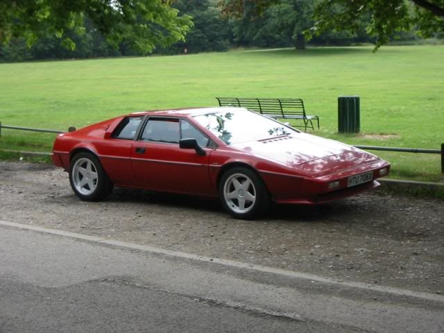
Take one 1981 Lotus Esprit S3
![Image]()
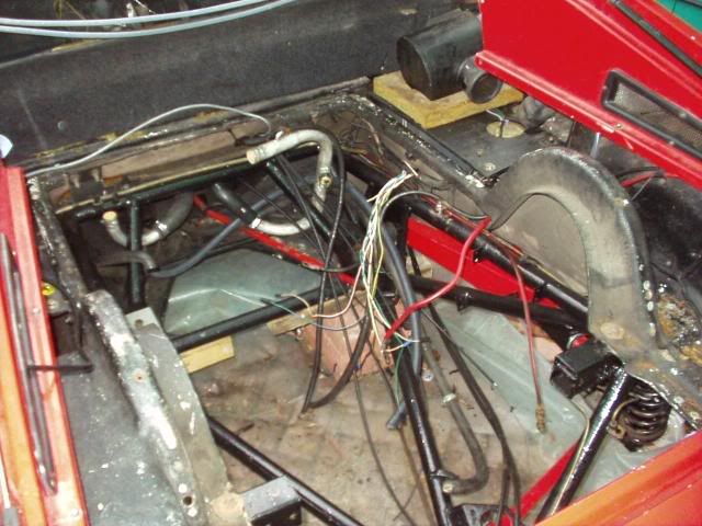
Pull out the 2.2litre 4 pot Lotus engine/Citroen gearbox and chuck in an Audi 4.2 V8 and six speed transaxle in here.
![Image]()
I have finally got hold of an ABZ from Germany and have balanced a 6 speed 01X gearbox onto it for giggles.
![Image]()
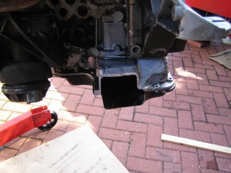
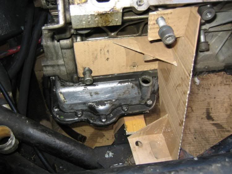
Got the tape measure out an I reckon it should be a pretty good fit as the ABZ is a fair bit shorter than the Lotus 912 which is coming out.
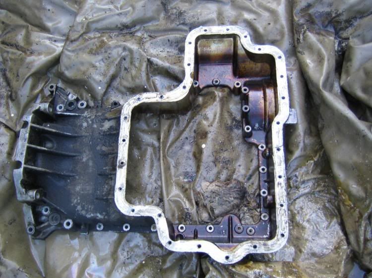
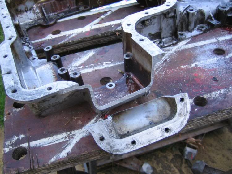
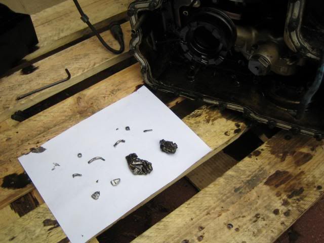
Unfortunatly this is were it all starts to go pear shaped. The engine suffered a bit as the sump got bent during shipping. So I whipped it off to straighten it and in the process this is what found in the sump.
![Image]()
Arse !!!!!!!!!!!
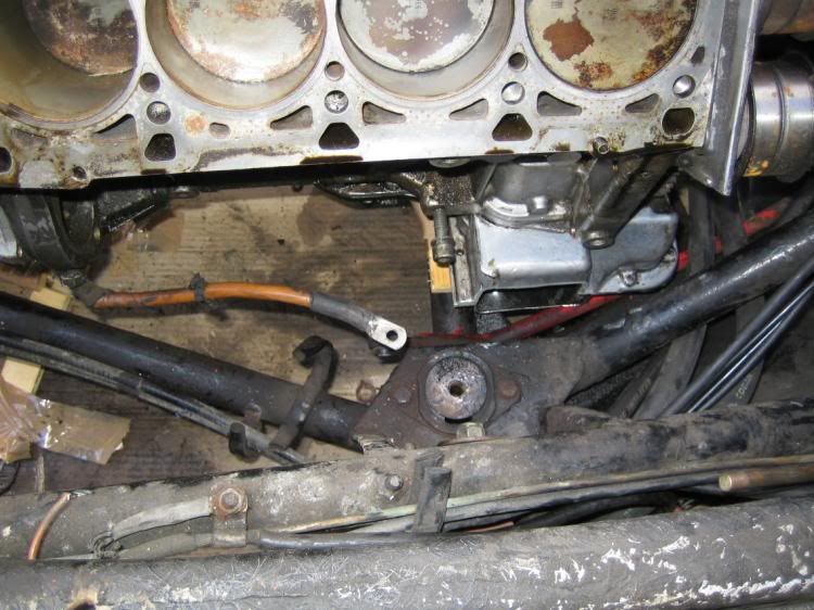
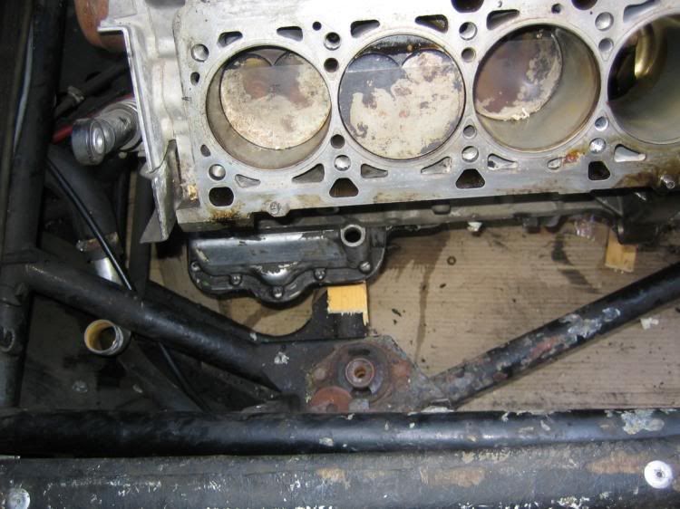
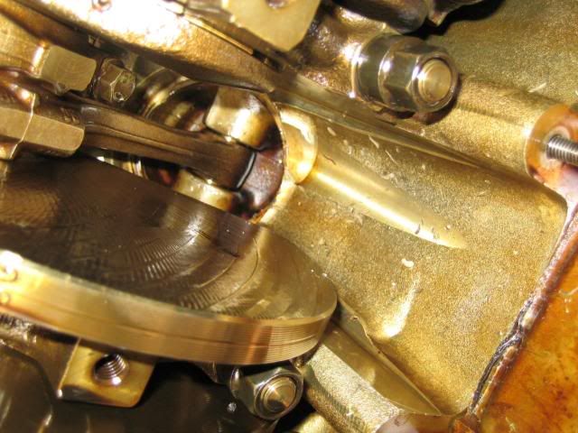
Had a look inside the crankcase to find plenty of dents from flying metal.
![Image]()
So what are the lumps that fell out of the bottom of the engine ??????
Time for a game, spot the difference between these 2 pictures ...............
![Image]()
![Image]()
The observant among you will notice that the piston oil spray bars are missing in the second picture.
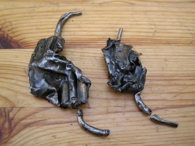
Laying the mashed bits of metal out it becomes evident that in fact 2 of them have come adrift.
![Image]()
So it is time to strip the engine down to investigate a bit further.
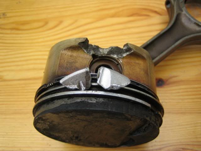
I find that piston number 8 has taken a hit from flying metal and has suffered a bit of weight reduction.
![Image]()
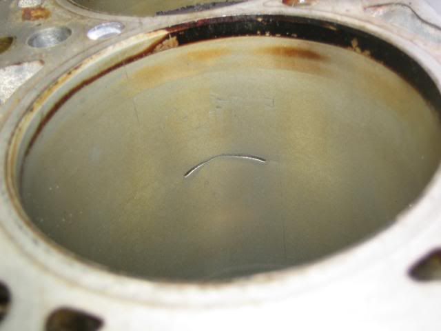
Unfortunately the cylinder wall hasn't come out scott free either.
![Image]()
So I now have a very large and heavy paper weight in my back garden.
On the bright side, the guy I bought the engine from is sending me another ABZ and doesn't want the old one back which means I have got a whole pile of spares")
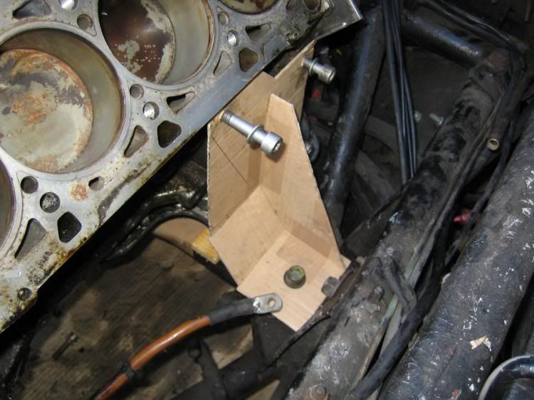
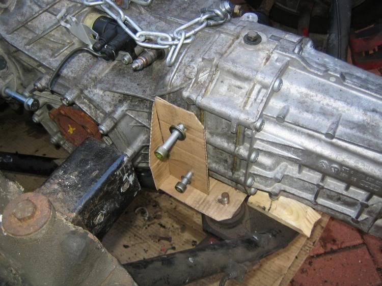
When the replacement turns up I can start cobbling the bits together ready to give the engine hoist some stick.
Andy
This is the plan........
Take one 1981 Lotus Esprit S3
Pull out the 2.2litre 4 pot Lotus engine/Citroen gearbox and chuck in an Audi 4.2 V8 and six speed transaxle in here.
I have finally got hold of an ABZ from Germany and have balanced a 6 speed 01X gearbox onto it for giggles.
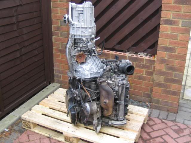
Got the tape measure out an I reckon it should be a pretty good fit as the ABZ is a fair bit shorter than the Lotus 912 which is coming out.
Unfortunatly this is were it all starts to go pear shaped. The engine suffered a bit as the sump got bent during shipping. So I whipped it off to straighten it and in the process this is what found in the sump.
Arse !!!!!!!!!!!
Had a look inside the crankcase to find plenty of dents from flying metal.
So what are the lumps that fell out of the bottom of the engine ??????
Time for a game, spot the difference between these 2 pictures ...............
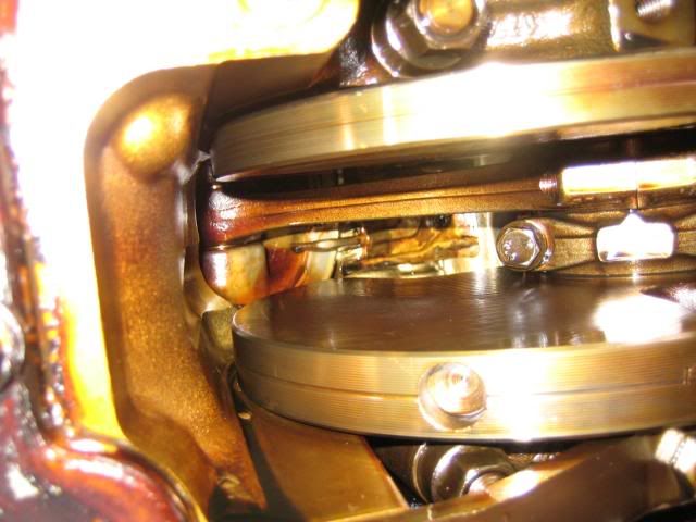
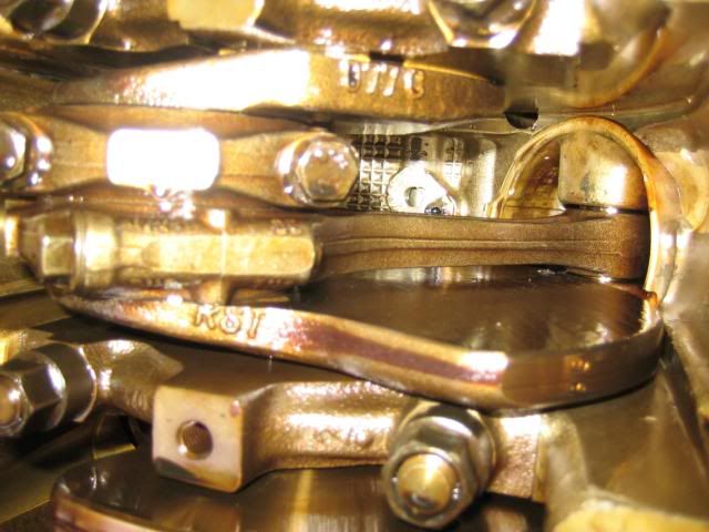
The observant among you will notice that the piston oil spray bars are missing in the second picture.
Laying the mashed bits of metal out it becomes evident that in fact 2 of them have come adrift.
So it is time to strip the engine down to investigate a bit further.
I find that piston number 8 has taken a hit from flying metal and has suffered a bit of weight reduction.
Unfortunately the cylinder wall hasn't come out scott free either.
So I now have a very large and heavy paper weight in my back garden.
On the bright side, the guy I bought the engine from is sending me another ABZ and doesn't want the old one back which means I have got a whole pile of spares
When the replacement turns up I can start cobbling the bits together ready to give the engine hoist some stick.
Andy