Thanks for all the comments fellas, very much appreciated, hope i can answer some of the queries tho!
")
Streamlining the intake guides isnt something ive put much effort into mainly as the material on these 20 valve heads is pretty tough, well, quite a bit tougher than that of other heads ive worked on like Toyota and Mazda, even the 10 valvers seem a lot softer and they cut a lot quicker and easier.
Access is a bit of a pain also and trying to get them all the same is one of those jobs that takes an age so as of yet ive not really experimented with that streamlining aspect.
I tend to lower the height and reduce the width which gets a gain, the only downside ive found is that when the guides go back in you can sometimes get a skewing effect ( its miniscule) that kicks the guide over to the side unsupported.
Although its very minor it can happen.
Having said that though, they always and i do mean always, go back in on the skew anyways, just they tend to aim in other directions, they never line up as previously and you notice it when you cut the seat with it being a tad offcentre.
One of the main problems i found that also causes that skew-over, is the interference fit between the guide and its bore in the head.
Every single time ive removed the oem guides ive measured them and found them to be 12.04-12.05mm.
But the aftermarket stuff seems to vary wildly, 12.08mm not being uncommon, meaning obviously that theyre way too tight, and it shows when you try to install them as the pressure gauge starts to rise too high.
Ive also found wide differences between the internal sizes of aftermarket guides such that the on set had more slop between the stem as a new item than the old worn out guide exhibited.
Incidentally i always press them out and in cold, using copper anti seize compound as a lubricant, i dont use any other lube like moly or motor oil as it dosnt work as well.
Cold pressing means you can get a feel for how much pressure its taking to push them in, you dont get that if you warm the head up or cool the guides down and in extreme cases if the interference fit is too much you can crack the head, plus you cant get the guide stuck if its at room temps along with the head.
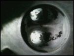
Aftermarket 20 valve guide...this ones from febi. This is 12.08mm, not the oem size of 12.04/5 mm.
Means i have to hone each one down to size so with 20 guides, it takes a while!
I nearly always reduce the guide height fractionally also, i never shave them to the surface of the port, itd compromise reliability too much.
They get a "bullet" nose applied to them also which reduces their intrusion into the airstream.
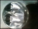
Heres the aftermarket one as they come to me on the far left, the others are as removed from the head.
Some almost finished ones.
Resized, shortened a fraction and bullet nosed.
Note: since this photo was taken ive refined the shape further, its all subtle stuff, but it does work.
Guide bosses arent entirely removed as id be scared of a breakthough into a water jacket for one thing and for another itd probably skew the guide even further offcentre than usual.
With the guides in you can how much less of an impact that whole area has in terms of restriction and its measurable too.
I did do some tests with "infilling" as on other heads ive found you can get an apparent ( not to my mind proven yet) flow increase by adding in material at a specific point just before the short side radius on these heads.
I was a little worried about adding in an epoxy resin filler to a clients property to have it dislodge later on so ive not investigated it further although it did show an apparent worthwhile increase of a few cfm.
Exhaust port bosses can be simply flushed to the surrounding area as its small anyway and is a carbon trap.
My old PEG10 valve grinder used a solid pilot that fits inside the guides and is tightened with a small screw at the base.
The actual grinding head with the integral motor sits over the pilot and is adjusted downwards until it starts to contact the seat.
The whole machine does an oscillation, both round the seat and in an orbit.
Seriously cool to watch but also somewhat frightening as it goes a fair speed.
Regarding the deshrouding aspect.
I did do a little work on that but i didnt seem to find any extra flow.
I suppose my testing regime could have been a little more rigorous really and maybe something would have become apparent.
Since ive got an AAN motor in my own quattro (unfinished as yet) there will doubtless come a time for the head to be removed for some work to be done on it, ill see what i can find out about deshrouding on these heads from that as and when.
Something else just sprung to mind, and this applies to any head, the manifolds need to outflow the ports.
I did some tests on an ABY and found they just about matched the bare port flows of the head when they were unmodified.
You tend to get some natural inherent flow bias due to the design with all these things anyway which you cant do anything about, but getting the runners of the manifold to outflow the ports is pretty vital or else all the work you put into the ports gets strangled by the manifold....
Making it larger than the ports and tapering it down internally is one way out of that.
This particular head came with a brand new AAN exhaust manifold that the client wanted matched to the ports.
With any exhaust you want to have the manifold at the face larger than the port so you have a step that discourages backflowing during overlap, pity the stock item is the wrong way around!
Looking out the exhaust port and a nice (or rather nasty) step presents itself.
Has to go.
Not only that, imagine youve just spent XXX$ on a new turbo and this breaks off inside and shatters the turbine...
Gave me a nice cut as well, teach me to stick my fingers down unauthorised holes...
Very hard to get any kind of grinding tool in there so i used an extended carbide burr on a small flexi to remove it all.
Anyways, i think ive drifted slightly off the thread topic.... hope this helps someone out.
OOps! Forgot the flowtest result.
Typical result, test carried out at 10" depression converted to 28".
Note: Ignore the apparent drop in flow at 7mm lift on the modified (top line obviously), thats a lifting error, and my fault.
Also dosnt show bare port flow on here.
Stock was-190cfm.
Modified- 215cfm max.
Flows dont quite intersect at max lift but thats not always possible to do anyway.