
hi guys,
so after trying to get rid of the coupe out of desperation for cash and unwillingness to put the time and effort into it, I have gotten a new found motivation and am going to finish her..
I owe that all to motorgeek....

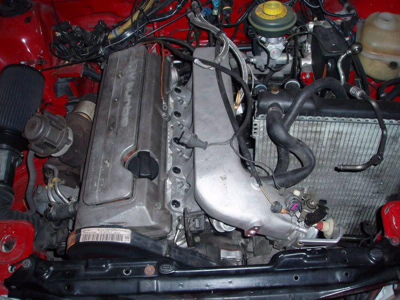
heres the car.....
![Image]()
![Image]()
![Image]()
![Image]()
since no one bought it, I am left with no other option but to hammer it our and enjoy what I had begun......now there is no more excuse for my wife, i gotta do what I got to do..... :woowoo:
I'm awaiting the aan harness and puter,
along with a need to purchase 034 throttle body adapter for their manifold to clear the stock powersteering pump location...........so I can use the stock serp belt setup....
I would like to go electric pump to clear the clutter, but I'm just doing necessities to get it running right now.....
the fun stuff can come down the road once I can prove to my wife that it is an actual car......
gotta buy also the intercooler pipe kit from 034....
I just hit up javad 2 days ago and haven't gotten a return mail, doesn't really seem like him......maybe the mail didn't go through or not...Javad?
got a aby s2 downpipe from josh, and i've got a muffler, so just need the middle pipe routed, (should be pretty easy and cheap)...
later gonna get the pretty 034 3in, but just doing essensials now....
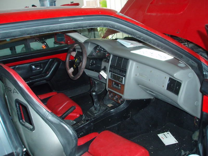
got the dash out and the climate box in the downtime awaiting the harness........
![Image]()
and since the dash is out i've got a black dash on its way to match the rest of the black interior....thanks RJ......
I started to work on the intercoolers to figure out which one to use and to see if I can salvage the endtanks since I'm on a budget.......
![Image]()
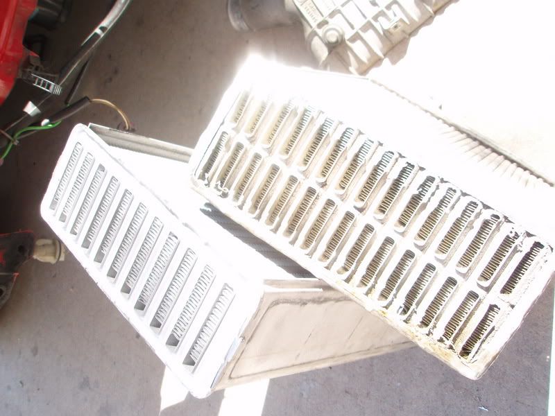
chopped off the endtanks and trying to decide which one to use....
got a bit deep on one, but didn't hurt anything........
the tanks off the porsche gt2 intercooler will fit on the other one,
I'd like to use it because it will fill in the bumper a bit more visually, but the gt2 core looks a lot more quality........much wider also.......
any imput? :thumbsup:
![Image]()
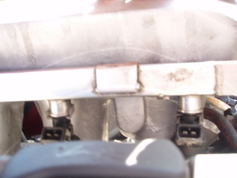
since the aan fuel rail didn't fit with the manifold, I chopped off some brackets so it fits, with the fuel line unscrewed.......... don't worry, i'm gonna clean up all the cutting later..........
![Image]()
![Image]()
so can I just chop off the end and flip it over and reweld it so the line sits on the outside of the rail? also,
do I just weld tabs to the fuel rail to tap into the manifold?
![Image]()
hope you all are down to help, I'm sure gonna need a good bit cuz Im definetly a novice with this car.....i've never touched it up until this point, but have come to be quite familiar since i've been addicted to motorgeek...........
thanks for the imput......
so after trying to get rid of the coupe out of desperation for cash and unwillingness to put the time and effort into it, I have gotten a new found motivation and am going to finish her..
I owe that all to motorgeek....
heres the car.....
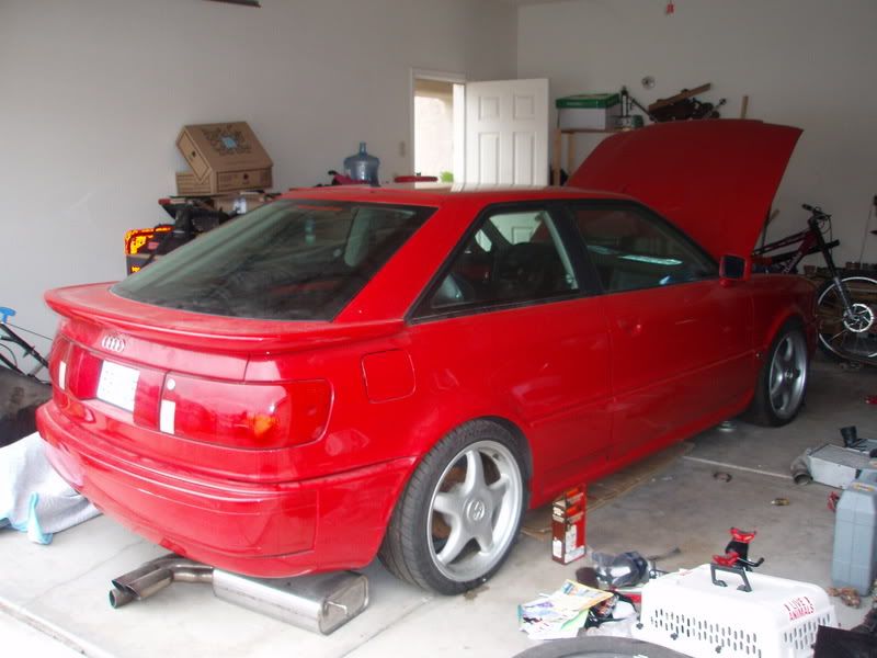
since no one bought it, I am left with no other option but to hammer it our and enjoy what I had begun......now there is no more excuse for my wife, i gotta do what I got to do..... :woowoo:
I'm awaiting the aan harness and puter,
along with a need to purchase 034 throttle body adapter for their manifold to clear the stock powersteering pump location...........so I can use the stock serp belt setup....
I would like to go electric pump to clear the clutter, but I'm just doing necessities to get it running right now.....
the fun stuff can come down the road once I can prove to my wife that it is an actual car......
gotta buy also the intercooler pipe kit from 034....
I just hit up javad 2 days ago and haven't gotten a return mail, doesn't really seem like him......maybe the mail didn't go through or not...Javad?
got a aby s2 downpipe from josh, and i've got a muffler, so just need the middle pipe routed, (should be pretty easy and cheap)...
later gonna get the pretty 034 3in, but just doing essensials now....
got the dash out and the climate box in the downtime awaiting the harness........
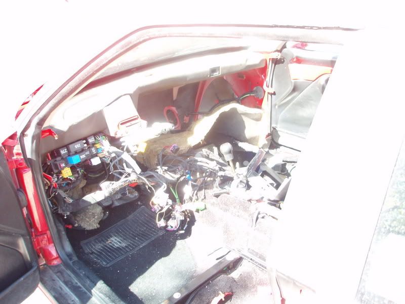
and since the dash is out i've got a black dash on its way to match the rest of the black interior....thanks RJ......
I started to work on the intercoolers to figure out which one to use and to see if I can salvage the endtanks since I'm on a budget.......
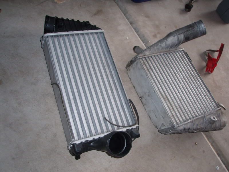
chopped off the endtanks and trying to decide which one to use....
got a bit deep on one, but didn't hurt anything....
....the tanks off the porsche gt2 intercooler will fit on the other one,
I'd like to use it because it will fill in the bumper a bit more visually, but the gt2 core looks a lot more quality........much wider also.......
any imput? :thumbsup:
since the aan fuel rail didn't fit with the manifold, I chopped off some brackets so it fits, with the fuel line unscrewed.......... don't worry, i'm gonna clean up all the cutting later..........
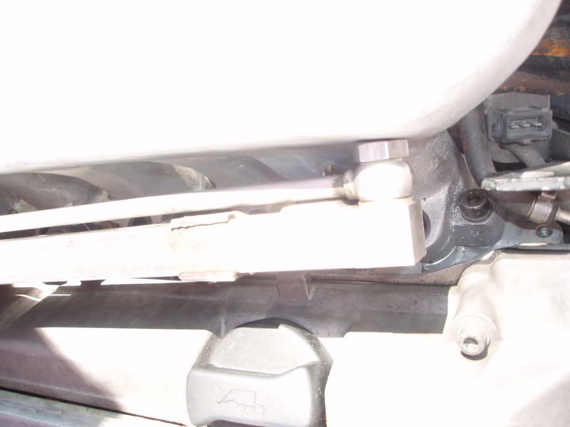
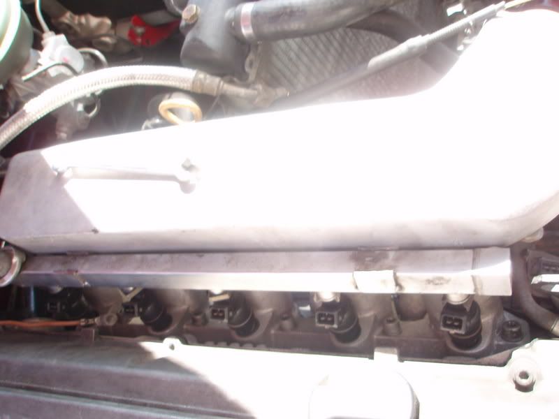
so can I just chop off the end and flip it over and reweld it so the line sits on the outside of the rail? also,
do I just weld tabs to the fuel rail to tap into the manifold?
hope you all are down to help, I'm sure gonna need a good bit cuz Im definetly a novice with this car.....i've never touched it up until this point, but have come to be quite familiar since i've been addicted to motorgeek...........
thanks for the imput......